
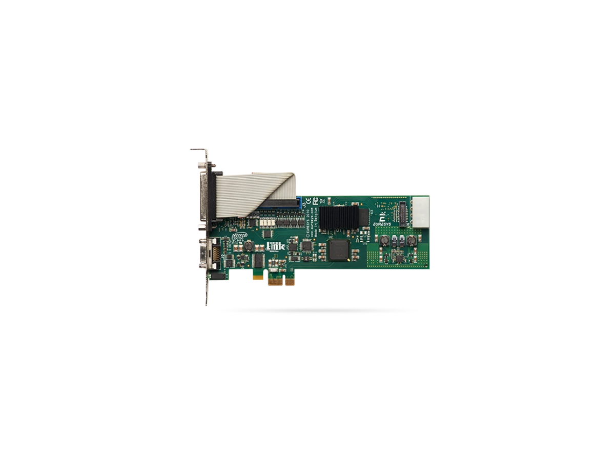
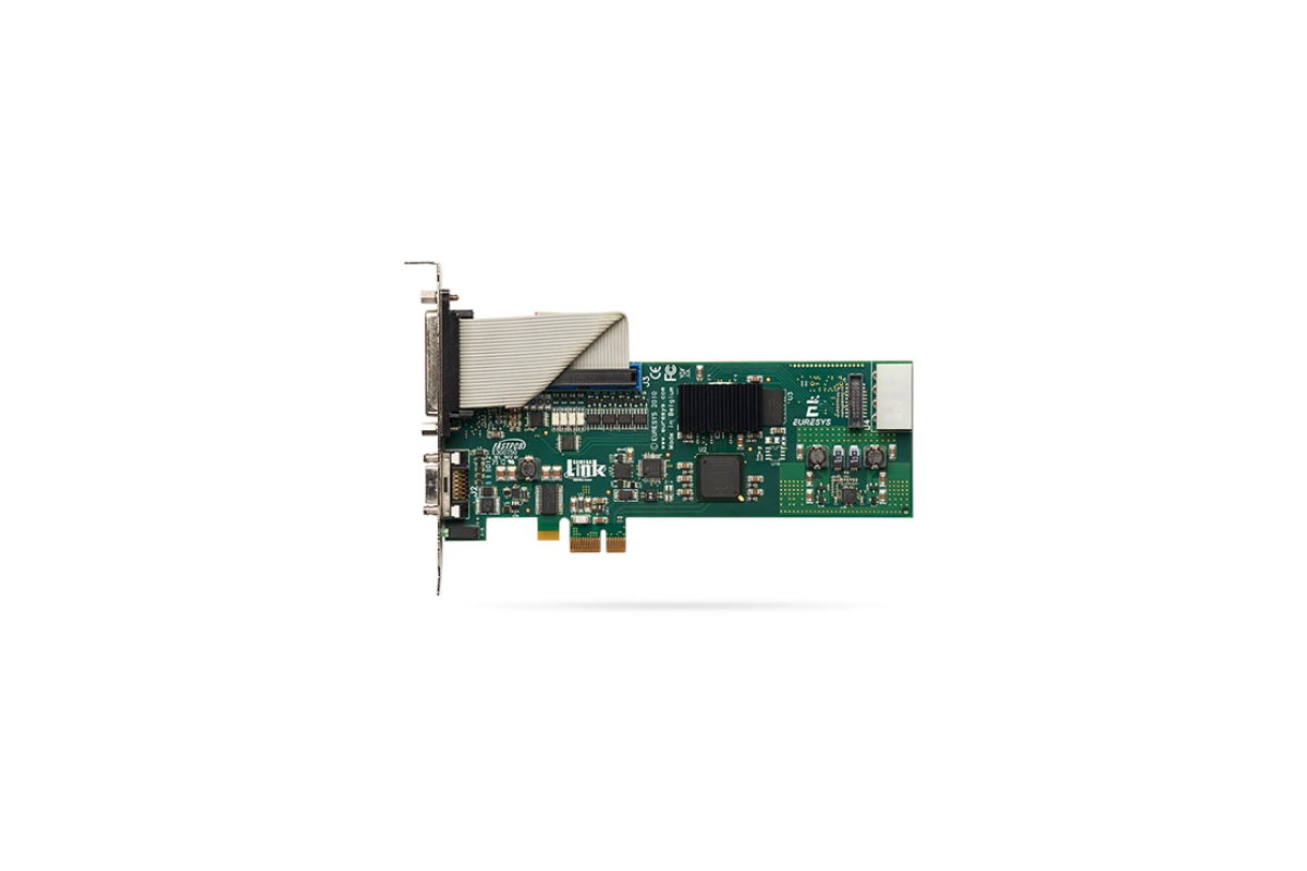
Grablink Base Key Features:
- Supports Base-configuration Camera Link cameras
- Deterministic, low-latency image acquisition with hardware triggering
- Direct Memory Access (DMA) for efficient data transfer and reduced CPU usage
- Flexible digital I/O for synchronization with encoders, lighting, and motion control
- Comprehensive SDK and driver support, including GenICam compatibility
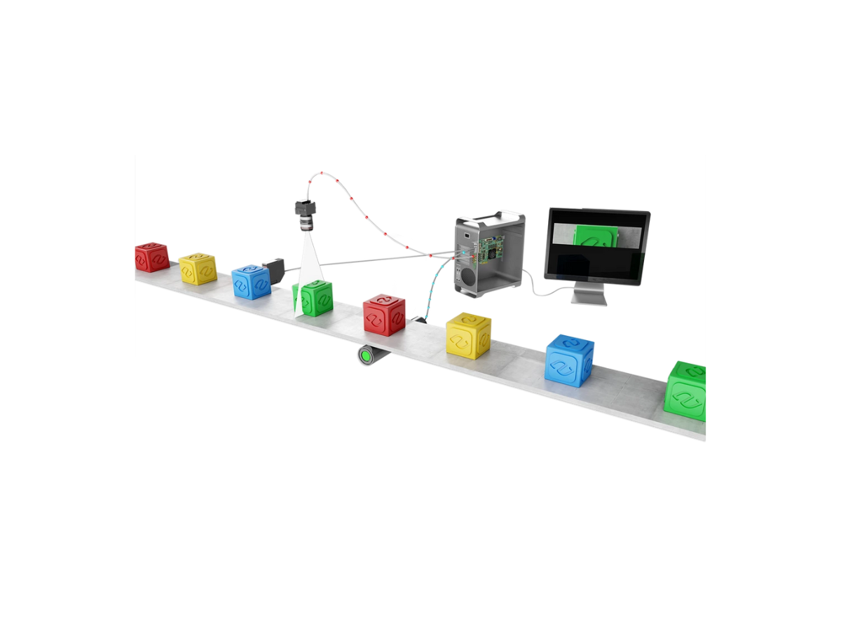
Ideal Solution For:
- Industrial inspection and automated quality control
- Electronics and semiconductor inspection
- High-speed packaging and print inspection
- Scientific and laboratory imaging
- OCR, pattern recognition, and general machine vision tasks
Technical Specifications
Specification |
Grablink Base |
Mechanical |
|
| Form Factor | PCI Express Card |
| Format | Low profile, half length, 1-lane PCI Express Card |
| Cooling | Air-cooling, fanless |
| Mounting | Low-profile or standard height, 1-lane or higher, PCI Express card slot |
| Connectors |
'A' on bracket: 26-pos SDR socket, CL base connector 'External I/O' on standard bracket: 25-pin 2-row female sub-D connector, I/O lines and power output 'Internal I/O' on PCB: 26-pin 2-row 0.1" pitch pin header with shrouding, I/O lines and power output 'Power Input' on module: 4-pin MOLEX power socket, 12 VDC power input for PoCL camera and I/O power |
| Dimensions | PCB L x H: 167.65 mm x 68.90 mm, 6.6 in x 2.71 in |
| Weight | 93g |
Host Bus |
|
| Standard | PCI Express 1.0 |
| Link Width | 1 lane |
| Link Speed | 2.5 GT/s (PCIe 1.0) |
| Max Payload Size | 1024 bytes |
| DMA | 32- and 64-bit |
| Peak Delivery Bandwidth | 256 MB/s |
| Power Consumption | Max. 4.5 W; Typ. 3.8 W (0.34 A @ 3.3V, 0.22 A @+12V) |
Camera/Video Inputs |
|
| Camera Interface Standard | Camera Link 2.0 |
| Max Link Speed | 85 MHz |
| Max Link Width | 24-bit (BASE) |
| Camera Power | PoCL |
| Connectors | One Shrunk Delta Ribbon (SDR) Miniature Camera Link (MiniCL) |
| Number of Cameras | 1 |
| Line-scan Supported | Yes |
| Max Aggregated Camera Data Transfer Rate | 2.04 Gbps (255 MB/s) |
| CL Configuration | Base or Lite |
| Camera Link Clock Frequency | From 20 MHz up to 85 MHz |
| PoCL | One PoCL SafePower compliant controller with overload, over-voltage and short-circuit protection |
| Camera Types | Grayscale and colour (RGB and Bayer) area- and line-scan cameras |
On-board Processing |
|
| On-Board Memory | 64 MB (32 MB for image data) |
| Image Data Stream Processing | Unpacking of 10-/12-/14-bit to 16-bit with selectable justification to LSb or MSb |
| Input LUT |
Monochrome: 8-bit, 10-bit or 12-bit per pixel, up to 500 MPixel/s RGB: 3x8-bit per pixel, up to 125 MPixel/s |
| Bayer CFA to RGB decoder |
Advanced interpolation method using average and median functions on a 3x3 kernel Up to 125 MPixel/s |
General Purpose Inputs/Outputs |
|
| Number of Lines |
10 I/O lines: 2 differential inputs (DIN) 4 isolated inputs (IIN) 4 isolated outputs (IOUT) |
| Electrical Specifications |
DIN: High-speed differential inputs, up to 5 MHz IIN: Isolated current-sense inputs with wide voltage input range up to 30V, compatible with totem-pole LVTTL, TTL, 5V CMOS drivers, RS-422 differential line drivers, potential free contacts, solid-state relays and opto-couplers IOUT: Isolated contact outputs compatible with 30V / 100mA loads NOTE: IIN and IOUT lines provide a functional isolation grade for the circuit technical protection. It does not provide an isolation that can protect a human being from electrical shock. |
| Filter Control | Glitch removal filter available only on input lines used as trigger sources. Configurable with five time constants. |
| Power Output | Non-isolated, +5V, 1A and +12V, 1A, with electronic fuse protection |
Software |
|
| Driver | MultiCam |
| Host PC OS |
Microsoft Windows 11, 10, 8.1, 7 , including the Server and the IoT Enterprise versions, for x86 (32-bit) and x86-64 (64-bit) processor architectures Linux for x86 (32-bit) and x86-64 (64-bit) processor architectures |
| APIs | MultiCam 32- and 64-bit binary libraries (Windows and Linux), for ISO-compliant C/C++ compilers |
| Momento Supported | Yes |